Abstract: Sliding bearing is a very important component of blast furnace blower unit, and improper installation, maintenance, and operation may cause sliding bearing failure. This article mainly discusses the reasons for the failure of the sliding bearing of the blast furnace blower unit, and proposes preventive measures that should be taken during installation, maintenance, and operation.
Keywords: blast furnace blower unit; Sliding bearings; Fault; Lubrication; Scraping tiles; Find the center; preventive measure
1 Preface
The sliding bearing of the blast furnace blower unit is the transition between the rotating and stationary parts of the unit, and its lifespan directly affects the length of the unit maintenance cycle. If the bearings cannot work safely, it will threaten the safe operation of the entire unit. If used properly, a pair of sliding bearings can operate continuously for at least three years, and some units have not replaced the bearings after ten years of use. If used improperly, it is also possible to continuously damage several sets of bearings within a month, which has occurred on some units. The most ideal situation for sliding bearings is to work under liquid friction conditions, because the working surfaces of the shaft and bearing are separated by a lubricating oil layer, so that there is almost no wear on the working surfaces of the shaft and bearing. Therefore, the ideal working period for sliding bearings should be very long. However, due to the frequent need to start and stop the machine during operation, resulting in changes in speed, improper handling of some details during installation and maintenance, as well as vibration, load changes, and poor lubrication during operation, all of which will damage the liquid friction conditions and cause bearing wear, resulting in bearing failure. If we understand the causes of sliding bearing faults in the blast furnace blower unit and take corresponding preventive measures, it is completely possible to eliminate bearing faults, extend bearing service life, and ensure safe and continuous operation of the blast furnace blower unit.
2 Analysis of the Fault Causes of the Sliding Bearing of the Blast Furnace Blowing Unit
The normal operation of sliding bearings depends not only on whether their manufacturing, installation, and maintenance quality meet the requirements, but also on the changes in the working conditions of the unit and whether the oil supply equipment can provide good oil supply. Specifically, in terms of manufacturing, installation, and maintenance, it is important to pay attention to the qualified casting quality of black gold. Black gold should not have defects such as detachment, cracks, or sand heels, and there should be no iron chips or sand particles in black gold; The installation clearance and tightening force of the bearings should meet the requirements, the bearing pads should be repaired and scraped correctly, and the center of the unit should be maintained correctly. The main points to pay attention to during operation are: monitoring the temperature of the bearing pads, lubricating oil temperature, and whether the oil supply equipment is working properly, as well as whether the vibration of the bearings is too large and whether there are any abnormal sounds. The possible faults of sliding bearings during operation are analyzed as follows:
(1) Insufficient or interrupted lubrication oil will cause an increase in bearing oil temperature, and in severe cases, it can cause the melting of bearing black gold. The main cause is: the main oil pump is damaged (internal clearance changes, severe wear occurs); The transmission part that drives the main oil pump is damaged; The oil inlet pipelines and connecting flanges of each bearing leak or break, and the oil pipelines are blocked; The oil level in the fuel tank is too low, causing the main oil pump to have insufficient oil suction or unable to draw oil.
(2) The lubricating oil is not clean, and there are sand particles and impurities inside the oil, which can cause damage to the oil film after being brought into the bearing shells. At this point, the temperature of the bearing shells and lubricating oil increases, which may even cause the bearing shells to melt.
(3) Excessive bearing vibration can cause black gold to fall off and crack, damaging the oil film.
(4) The cooling water of the oil cooler is interrupted, and the temperature of the oil entering the bearing is too high. The viscosity of the oil decreases significantly, and the heat of the journal cannot be taken away, and an oil film cannot be formed inside the bearing shell.
(5) Water in the lubricating oil causes damage to the oil film in the bearing. The main source of water in lubricating oil is: steam leakage from the turbine shaft seal, excessive clearance between the shaft end seals, and leakage into the bearings. If the pressure of the cooling water flowing through the oil cooler is greater than the oil pressure, the cooling water will leak into the oil when the heat exchange tube leaks.
(6) During operation, due to excessive thermal deformation of the bearing shell, the contact surface between the rotor journal and the bearing pad is subjected to uneven force, resulting in incomplete contact between the bearing pad and the journal along the length direction, resulting in partial wear of the black metal and bearing heating. This situation is more likely to occur on cylindrical bearing shells.
3 Preventive Measures for Sliding Bearing Fault of Blast Furnace Blowing Unit
Based on the above analysis, the failure of the sliding bearing of the blast furnace blower unit may be caused by manufacturing, installation and maintenance, or operation. Generally speaking, the current manufacturing technology is very mature, and there are strict factory controls. Manufacturing quality issues are rare. The failure of the sliding bearing of the blast furnace blower unit is mainly caused by poor handling of some details in installation and maintenance and improper operation. Therefore, preventing the failure of the sliding bearing of the blast furnace blower unit mainly starts from two aspects: installation and maintenance and operation.
3.1 Preventive Measures for Installation and Maintenance
According to the actual situation, it has been found that improper scraping of the bearing pads and improper alignment of the unit during the installation and maintenance of the blast furnace blower unit are the main reasons for bearing failures. Therefore, correct scraping of the bearing pads and correct alignment of the unit center are the key to preventing the sliding bearing failure of the blast furnace blower.
3.1.1 Correct scraping of bearing shells
According to the working principle of high-speed sliding bearings, the most important thing when repairing bearing shells is to find ways to ensure the shape, size, and smoothness of the bearing shells. The shape of the bearing pad, for cylindrical bearings, the correct shape is a complete circle, and the diameter of the cylindrical bearing pad should be slightly larger than the diameter of the working shaft, ensuring the formation of the correct wedge-shaped gap. For elliptical bearings, the upper and lower halves are also circular and have equal radii, except that the upper and lower halves are not concentric, and the radius of the bearing pad is larger than the radius of the working journal. The wedge shrinkage of elliptical bearings is larger than that of cylindrical bearings. Whether for cylindrical bearings or elliptical bearings, the higher the requirement for the surface smoothness of the bearing pads, the better.
Manual scraping of bearings requires the use of a dummy shaft (also known as a measuring shaft), which has a diameter greater than the diameter of the working journal. In other words, the diameter of the dummy shaft is equal to the diameter of the working shaft plus the expected oil wedge clearance. When repairing and scraping the bearing pads, match them with the dummy shaft. The scraped bearing pads should be circular, with a diameter difference between the bearing pads and the working journal, an expected wedge-shaped gap, and the working journal should be in line contact with the lower part of the bearing pads. Due to machining errors and deformation during scraping, the actual contact is a narrow surface, which should generally not exceed 10mm along the axial direction. Each half of the bearing pads scraped according to the dummy axis should match the dummy axis. The higher the smoothness of scraping, the more conducive it is to the formation of oil film. Especially in the lower part of the bearing shell at 60-70 °, it is generally the area where the oil film generates oil pressure, so it must be very smooth and clean. Within this range, oil holes and grooves are not allowed, and defects such as pores and sand holes are not allowed. Moreover, it is not allowed to scrape pits to store oil. The drawing indicates that the bearing contact angle is between 60 and 70 °, indicating that this range is the oil film pressure zone and must be carefully controlled. It does not mean that this range should be scraped to match the working journal. How to determine the size of the dummy axis? How much larger is its diameter than the working journal? This is determined based on the expected wedge gap size. For cylindrical bearings, the diameter of the dummy shaft should be equal to the diameter of the working journal plus the top clearance.
3.1.2 Correctly locate the unit center
According to the actual situation, it has been found that the method of finding the center of the unit is incorrect. The error in finding the center of the unit is too large, or it can be found in the cold state, but the center moves too much during the hot state, which can cause significant vibration, bearing wear, noise, and unstable operation. At the same time, it also increases the load on the bearing, which is prone to bearing failure. There are two main reasons for the large error in center finding during cold state: ① not being careful enough; ② The center finding tool system itself has significant errors. To correctly locate the unit center, the following should be achieved:
(1) Confirm whether the tool system for finding the center is reliable. Place the dial gauge on its own axis and check that it is at the top point. When the surface is facing up, rotate the dial gauge 180 ° with the axis at the bottom point. When the surface is facing down, check if there is any change in the reading. This can determine if there is a problem with the centering tool system.
(2) When finding the center, the two shafts need to be marked with positioning marks and rotated simultaneously to eliminate machining errors of the parts.
(3) When finding the center, at least four points should be found: up, down, left, and right. The sum of two numbers on any diameter of the outer circle should be a constant. Therefore, when verifying data, regardless of the actual deviation of the center, the sum of the upper and lower numbers should be equal to the sum of the left and right numbers; When finding the end face opening, if the axial positions of the two shafts can be relatively fixed, the data of the end face opening found should also be equal to the sum of the upper and lower numbers and the sum of the left and right numbers, regardless of the actual size of the opening.
(4) You should search for the center three times in a row. You can search clockwise and counterclockwise once, and move the center finding tool 180 ° relative to each other to search again. The results of several center finding attempts should be the same.
(5) When locating the center, the hot deformation of the unit should be considered based on the design parameters of the unit, and pre compensation should be carried out when locating the center in the cold state.
3.2 Preventive measures for operation
(1) Continuously monitor the operation of oil supply equipment (main oil pump, auxiliary oil pump, oil cooler, pressure reducing valve, overflow valve, oil tank, oil injector, etc.) to ensure their normal operation. The working condition of these equipment is mainly judged based on the inlet oil pressure and oil temperature. If any abnormalities are found, corresponding measures should be taken immediately for wax application.
(2) Continuously monitor the bearing temperature, and if any changes are found in the bearing temperature, the cause must be identified and eliminated. The temperature of thrust bearings should be given more attention. Even if there is a slight increase in temperature, it may be due to severe wear of the black metal. Sometimes, even if the temperature of the thrust bearing only rises by 1-2 ℃, the black metal has already worn a lot. If the temperature rises by 8-15 ℃, not only the black metal has melted, but also the thrust pads themselves have worn very severely.
(3) Regularly observe the vibration value of the bearings and the axial displacement of the rotor, and pay attention to the pressure changes in each monitoring section of the steam turbine. If any abnormalities are found, they should be immediately analyzed, the cause identified, and dealt with decisively.
(4) Strictly monitor the operating conditions of the blower and never allow it to operate under unstable conditions.
4 Conclusion
The blast furnace blower unit is one of the key equipment in the blast furnace smelting system. If an accident occurs, the direct and indirect losses caused will be enormous. By taking corresponding preventive measures, the failure of sliding bearings can be avoided. Proper installation, maintenance, and operation ensure that the sliding bearings can operate safely and stably for a long time.
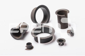
More about Epen EUR Bushing:
EUR is two-layer structure, which consists of a bronze mesh Laminated with PTFE Tape. The weight of fininal products is lighter and easy to install due to advantages of this structure. Automotive door hinges is one of typical applications.